Configure Interface Devices
- The 'Network Configuration' tab lets you view and configure network interfaces that have been added to your appliance. You can also create virtual LAN from this screen.
- By default, port 1 on the virtual machine is automatically configured for LAN with IP 192.168.0.15.
- The number of ports shown in the configuration screen depends on the number of network adapters added to the VM. These ports will be shown as Port 2, Port 3, Port 4 etc.
- Click 'Network' > 'Interfaces' to open the network and VLAN configuration screens:
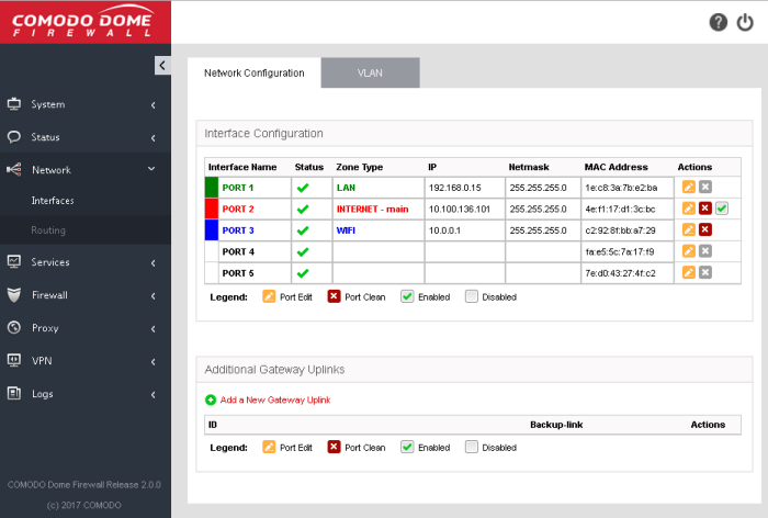
The network configuration screen has two panes:
- Interface Configuration - Shows interface devices connected to the ports of the virtual appliance along with their configuration and connection status. Allows you to add and manage network zone interfaces. This section explains about how to configure the interface devices.
- Additional Gateway Uplinks - Shows nodes in your internal network zones configured as gateway devices for the DFW virtual appliance to connect to internet. Allows you to add and manage gateway devices. See next section Add and Manage Gateway Uplink Devices for more details.
Interface Configuration
The
interface configuration table shows port configuration details for
your interface devices. You can add new interface connections and
enable/disable existing connections from this interface.
|
Interface Configuration Table - Column Descriptions |
|
|---|---|
|
Column Header |
Description |
|
Interface Name |
Name of the FW port. The font color indicates the type of network zone to which the port is connected. Red - External networks, like WAN, for internet connection. Green - Local Area Network to which workstations are connected. |
|
Status |
Link status of the interface device. The status can be one of the following: Green Tick - Link is active. Red Cross - The link is not active. Question Mark - No information about the link from the device driver. |
|
Zone Type |
The network zone type of the interface. The network zone can be one of the following:
|
|
IP |
The IP address of the interface device connected to the port. |
|
Netmask |
The netmask of the network zone connected through the interface. |
|
MAC Address |
The Media Access Control (MAC) address of the interface. |
|
Actions |
Displays control buttons for editing and deleting the port entries.
|
The following sections explain how to configure the network zone interfaces:
Configure untrusted external
network zones like WAN for connecting to the Internet
The setup for external networks involves choosing the physical port to which the interface device for main uplink is connected and then configuring network parameters and preferences.
|
Tip: You can add more uplinks for fail-over and load sharing to different ports at a later time from the 'Network' > 'Interfaces' > 'Network Configuration' screen using the same procedure. Also you can add nodes among your internal network and connected to internet as gateway uplink devices to the virtual appliance through the same interface. See Add and Manage Gateway Uplink Devices for more details. |
To configure the external network
zone
-
Click the edit icon
 in the row of the
port to which the interface device for connecting to external
network/internet is plugged-in.
The pane for configuring the interface device will open, with the row of the selected port highlighted.
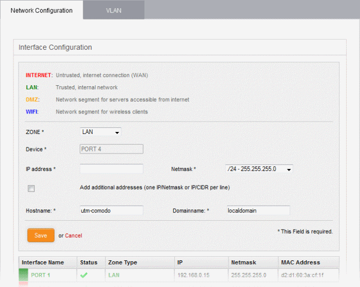
- Zone - Select 'Internet' from the drop-down. The configuration options for external network interface devices will appear:
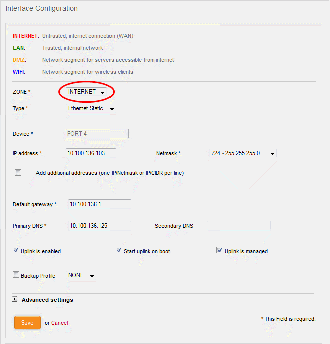
- Type - Choose the interface type through which the virtual appliance is connected to the internet. The available options are:
- ETHERNET STATIC - The external network interface is in a LAN and has a fixed IP address and netmask. An example is a router in which the DFW virtual appliance is assigned a fixed IP address.
- ETHERNET DHCP - The external network interface receives its network configuration through dynamic host control protocol (DHCP) from a local server, router, or modem.
- PPPoE - The external interface is connected to an ADSL modem through an Ethernet cable. Select this option only if the modem uses the Point-to-Point Protocol over Ethernet (PPPoE) protocol to connect to the service provider.
The following sections explain configuration parameters for each interface type:
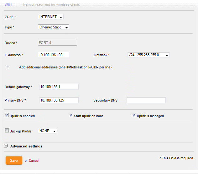
- Configure the following for the external network zone
Device Settings
- Device - The port to which the interface device is connected. The port is pre-selected.
- IP Address - Enter the IP address of the interface device
- Netmask - Choose the network mask containing the possible masks from the drop-down (e.g. /24 - 255.255.255.0)
- Add additional addresses - If additional IP address(es)/netmask(s) are to be added to the interface, select the 'Add additional addresses' checkbox and enter the additional IP address(es)/netmask(s) of different subnets one by one per line.
- Default gateway - Enter the IP address of the default gateway through which the virtual appliance connects to internet in the 'Default Gateway' text box
- DNS Settings - Enter the IP addresses/hostnames of the primary and secondary DNS servers to be used in the respective fields.
Uplink Settings
- Uplink is Enabled - The uplink will be activated immediately after it is created. Deselect this if you don't want to enable the uplink device at this time. You can enable the uplink later in two ways:
- Interface configuration screen – Enable the port in the Interface Configuration screen
- Dashboard – Enable the 'Active' checkbox beside the uplink in the 'Uplinks' box. See the section explaining the Uplinks box in the 'Dashboard' for more details.
- Start uplink on boot - The uplink will start automatically on every restart of the DFW virtual appliance. Deselect this checkbox if you want to manually start the uplink only when required.
- Uplink is managed - The uplink will be managed by Dome Firewall and its details will be displayed in the Dashboard. Deselect this option if you do not want the uplink details to be displayed in the Dashboard. You can switch the uplink to managed state at any time by selecting the 'Managed' checkbox beside the uplink in the Dashboard. See section explaining the Uplinks box in the 'Dashboard' chapter for more details.
- Backup Profile - Select this checkbox if you want to specify an alternative uplink connection to be activated in the event this uplink fails and choose the alternative uplink device from the drop-down.
- Additional Link check hosts - The uplink reconnects automatically after a time period set by your ISP, in the event of a connection failure. If you want the virtual appliance to check whether the uplink has connected successfully, you can try to ping known hosts in an external network. Enabling this option will reveal a text field where you should enter a list of one or more perpetually reachable IP addresses or hostnames. One of the hosts could be your ISP's DNS server or gateway.
Advanced Settings:
The Advanced Settings pane allows you to specify the MAC address and the Maximum Transmission Unit (MTU) of the data packets for the interface device. These settings are optional. If you need to specify custom values for these fields, click on the '+' sign beside 'Advanced Settings' to expand the 'Advanced Settings' pane.
- Use custom MAC address - The virtual appliance has the capability to automatically detect the MAC address of the device connected to the port specified and populates the same in the MAC address column. If you need to specify a different MAC address to override and replace the default MAC address of the external interface, select the ' Use custom MAC address' checkbox and enter the MAC address in the text box that appears below the checkbox.
- Reconnection timeout - Specify the maximum time period (in seconds) that the uplink should attempt to reconnect in the event of a connection failure. The reconnection timeout period depends on the ISP configuration. If you are unsure, leave this field blank.
- MTU - Enter the Maximum Transmission Unit (MTU) of the data packets that can be sent over the network.
- Click 'Save'.
A confirmation dialog will be displayed.

- Click OK.
The virtual appliance will restart for your settings to take effect.
- Network configuration activities like date, time, type of event, subject id, component name and the event outcome are logged.
|
Tip:
You can edit the network configuration e.g. for changing selected
parameters like hostname or the network range of a zone, at any
time depending on changes in your network. Click Network >
Interface, click the 'Edit icon' |
- Configure the following for the external network zone with Ethernet DHCP interface
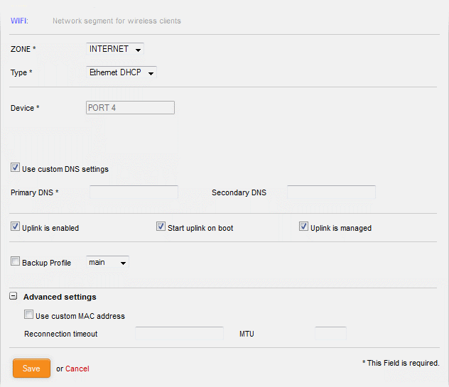
Device Settings
- Device - The port to which the interface device is connected. The port is pre-selected.
- DNS Settings - Select whether the DNS servers are to be automatically or manually assigned. If the latter, select the 'Use Custom DNS Settings' checkbox and enter the IP addresses/hostnames of the your primary and secondary DNS servers.
Uplink Settings
- Uplink is Enabled - The uplink will be activated immediately after it is created.Deselect this if you don't want to enable the uplink device at this time. You can enable the uplink later in two ways:
- Interface configuration screen – Enable the port in the Interface Configuration screen
- Dashboard – Enable the 'Active' checkbox beside the uplink in the 'Uplinks' box. See the section explaining the Uplinks box in the 'Dashboard' for more details.
- Start uplink on boot - The uplink will start automatically on every restart of the DFW virtual appliance. Deselect this checkbox if you want to manually start the uplink when required.
- Uplink is managed - The uplink will be managed by Dome Firewall and its details displayed in thedashboard. Deselect this option if you do not want the uplink to be listed in the dashboard. You can switch the uplink to managed state at any time by selecting the 'Managed' checkbox beside the uplink in the dashboard.See section explaining the Uplinks box in the 'Dashboard' chapter for more details.
- Backup Profile - Select if you want to specify an alternative uplink connection which is activated in the event this uplink fails. You need to choose the alternative uplink device from the drop-down.
- Additional Link check hosts – The uplink reconnects automatically after a time period set by your ISP in the event of a connection failure. If you want the virtual appliance to check whether the uplink has connected successfully, you can try to ping known hosts in an external network.
- Enabling this option will reveal a text field where you should enter a list of one or more perpetually reachable IP addresses or hostnames. One of the hosts could be your ISP's DNS server or gateway.
Advanced Settings:
The 'Advanced Settings' pane allows you to specify the MAC address and the Maximum Transmission Unit (MTU) of the data packets for the interface device. These settings are optional. If you need to specify custom values for these fields, click on the '+' sign beside 'Advanced Settings' to expand the 'Advanced Settings' pane.
- Use custom MAC address - By default, the virtual appliance automatically detects the MAC address of the device connected to the specified port and populates the MAC address column with this information. If you need to specify a different MAC address (and replace the default MAC address of the external interface), select the ' Use custom MAC address' checkbox and enter the MAC address in the text box that appears below the checkbox.
- Reconnection timeout - Specify the maximum time period (in seconds) that the uplink should attempt to reconnect in the event of a connection failure. The reconnection timeout period depends on the ISP configuration. If you are unsure, leave this field blank.
- MTU - Enter the Maximum Transmission Unit (MTU) of the data packets that can be sent over the network.
- Click 'Save'.
- Network configuration activities like date, time, type of event, subject id, component name and the event outcome are logged.
|
Tip:
You can edit the network configuration e.g. for changing selected
parameters like hostname or the network range of a zone, at any
time depending on changes in your network. Click Network >
Interface, click the 'Edit icon' |
- Configure the following for external network zones with PPPoP interface
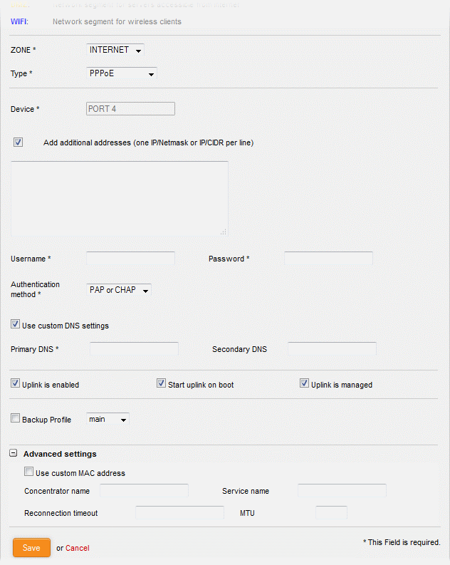
Device Settings
- Device - The port to which the interface device is connected. The port is pre-selected.
- Add additional addresses - If additional IP address(es)/netmask(s) are to be added to the interface, select the 'Add additional addresses' checkbox and enter the additional IP address(es)/netmask(s) of different subnets one by one per line.
- Username - Enter the login username for internet connection as provided by your Internet Service Provider (ISP)
- Password - Enter the login password as provided by your ISP for internet connection
- Authentication Method - Enter the method of authentication used by your ISP for your device to connect to internet from the drop-down. The options available are: Password Authentication Protocol (PAP); Challenge Handshake Authentication Protocol (CHAP); or both. If you are not sure about the authentication method, choose PAP or CHAP (Default).
- DNS Settings - Select whether the DNS servers are to be automatically assigned or manually assigned. If the later, select the Use 'Custom DNS Settings' checkbox and enter the IP addresses/hostnames of the primary and secondary DNS servers to be used.
Uplink Settings
- Uplink is Enabled - The uplink will be activated immediately after it is created. Deselect this if you don't want to enable the uplink device at this time. You can enable the uplink later in two ways:
- Interface configuration screen – Enable the port in the Interface Configuration screen
- Dashboard – Enable the 'Active' checkbox beside the uplink in the 'Uplinks' box. See the section explaining the Uplinks box in the 'Dashboard' for more details.
- Start uplink on boot - The uplink will start automatically on every restart of the DFW virtual appliance. Deselect this checkbox if you want to manually start the uplink only when required.
- Uplink is managed - The uplink will be managed by Dome Firewall and its details will be displayed in the Dashboard. Deselect this option if you do not want the uplink details to be displayed in the Dashboard. You can switch the uplink to managed state at any time by selecting the 'Managed' checkbox beside the uplink in the Dashboard. See section explaining the Uplinks box in the 'Dashboard' chapter for more details.
- Backup Profile - Select this checkbox if you want to specify an alternative uplink connection to be activated in the event this uplink fails and choose the alternative uplink device from the drop-down.
- Additional Link check hosts - The uplink reconnects automatically after a time period set by your ISP, in the event of a connection failure. If you want the virtual appliance to check whether the uplink has connected successfully, you can try to ping known hosts in an external network. Enabling this option will reveal a text field where you should enter a list of one or more perpetually reachable IP addresses or hostnames. One of the hosts could be your ISP's DNS server or gateway.
Advanced Settings:
The Advanced Settings pane allows you to specify the MAC address and the Maximum Transmission Unit (MTU) of the data packets for the interface device. These settings are optional. If you need to specify custom values for these fields, click on the '+' sign beside 'Advanced Settings' to expand the 'Advanced Settings' pane.
- Use custom MAC address - The virtual appliance has the capability to automatically detect the MAC address of the device connected to the port specified and populates the same in the MAC address column. If you need to specify a different MAC address to override and replace the default MAC address of the external interface, select the ' Use custom MAC address' checkbox and enter the MAC address in the text box that appears below the checkbox.
- Concentrator name - Enter the identifier of the remote access concentrator setup by your service provider (Optional, usually not needed).
- Service Name - Enter the name of your ISP (Optional, usually not needed).
- Reconnection timeout - Specify the maximum time period (in seconds) that the uplink should attempt to reconnect in the event of a connection failure. The reconnection timeout period depends on the ISP configuration. If you are unsure, leave this field blank.
- MTU - Enter the Maximum Transmission Unit (MTU) of the data packets that can be sent over the network.
- Click 'Save'.
- Network configuration activities like date, time, type of event, subject id, component name and the event outcome are logged.
|
Tip:
You can edit the network configuration e.g. for changing selected
parameters like hostname or the network range of a zone, at any
time depending on changes in your network. Click 'Network' >
'Interface', click the 'Edit icon' |
Configure a trusted internal
network zone (e.g. LAN)
The setup for internal network zone involves choosing the physical port to which the interface device for LAN is connected and then configuring network parameters and preferences for the same.
To configure the internal network zone
- Click on the edit icon
 in the row of the
port to which the interface device for connecting to the LAN zone is
plugged-in.
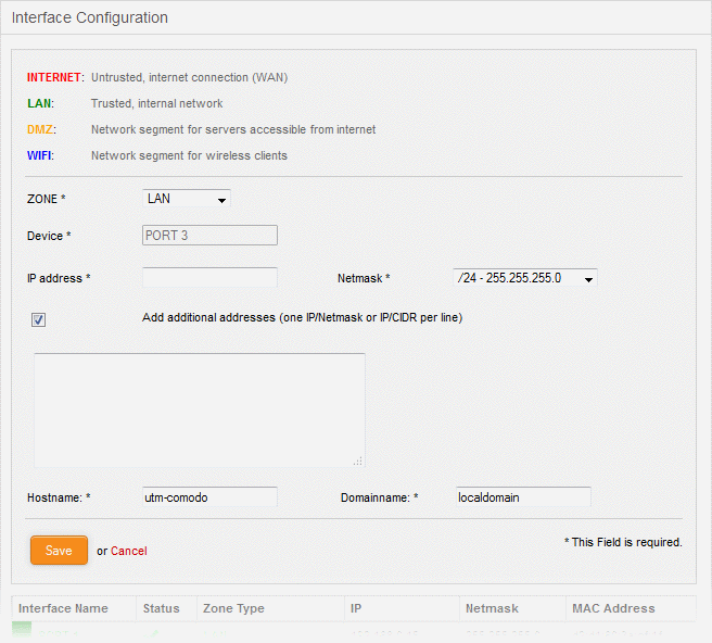
- Zone - Select 'LAN' from the drop-down. The configuration options for the internal network interface device will appear:
- Device - The port to which the interface device is connected. The port is pre-selected.
- IP Address - Enter the IP address of the interface device, as pre-configured in the network
- Netmask - Choose the network mask containing the possible masks from the drop-down (e.g. /24 - 255.255.255.0)
- Add additional addresses - If additional IP address(es)/netmask(s) are to be added to the interface, select the 'Add additional addresses' checkbox and enter the additional IP address(es)/netmask(s) of different subnets one by one.
- Hostname and Domainname - Enter the host name of your network server and the domain name of your network in the respective text fields
- Click 'Save'.
A confirmation dialog will be displayed.

-
Click OK.
The virtual appliance will restart for your settings to take effect.
-
Network configuration activities like date, time, type of event, subject id, component name and the event outcome are logged.
|
Tip:
You can edit the network configuration e.g. for changing selected
parameters like hostname or the network range of a zone, at any
time depending on changes in your network. Click Network >
Interface, click the 'Edit icon' |
DMZ setup involves choosing the port to which the DMZ device is connected then configuring network parameters and preferences.
To configure the DMZ network zone
- Click the edit icon
 in the row of the port
used by the DMZ device
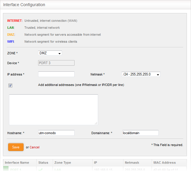
- Zone - Select 'DMZ' from the drop-down. The configuration options for the DMZ network interface device will appear:
- Device - The port to which the interface device is connected. The port is pre-selected.
- IP Address - Enter the IP address of the interface device, as pre-configured in the network
- Netmask - Choose the network mask containing the possible masks from the drop-down (e.g. /24 - 255.255.255.0)
- Add additional addresses - If additional IP address(es)/netmask(s) are to be added to the interface, select the 'Add additional addresses' checkbox and enter the additional IP address(es)/netmask(s) of different subnets one by one.
- Hostname and Domainname - Enter the host name of your network server and the domain name of your network in the respective text fields
- Click 'Save'.
A confirmation dialog will be displayed.

- Click OK.
The virtual appliance will restart for your settings to take effect.
- Network configuration activities like date, time, type of event, subject id, component name and the event outcome are logged.
|
Tip:
You can edit the network configuration at any time. To do so,
click Network > Interface, click the 'Edit icon' |
The setup for the WiFi zone involves choosing the physical port to which the interface device for Wi-Fi is connected and then configuring network parameters and preferences for the same.
To configure the Wi-Fi network zone
- Click on the edit icon
 in the row of the
port to which the interface device for connecting to the Wi-Fi zone
is plugged-in.
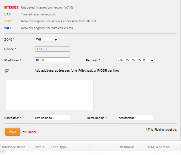
- Zone - Select 'Wi-Fi' from the drop-down. The configuration options for the Wi-Fi network interface device will appear:
- Device - The port to which the interface device is connected. The port is pre-selected.
- IP Address - Enter the IP address of the interface device, as pre-configured in the network
- Netmask - Choose the network mask containing the possible masks from the drop-down (e.g. /24 - 255.255.255.0)
- Add additional addresses - If additional IP address(es)/netmask(s) are to be added to the interface, select the 'Add additional addresses' checkbox and enter the additional IP address(es)/netmask(s) of different subnets one by one.
- Hostname and Domainname - Enter the host name of your network server and the domain name of your network in the respective text fields
- Click 'Save'. A confirmation dialog will be displayed.

- Click OK.
The virtual appliance will restart for your settings to take effect.
- Network configuration activities like date, time, type of event, subject id, component name and the event outcome are logged.
|
Tip:
You can edit the network configuration e.g. for changing selected
parameters like hostname or the network range of a zone, at any
time depending on changes in your network. Click Network >
Interface, click the 'Edit icon' |


 - Disconnects the interface and clears the
port.
 - Indicates whether the port is enabled or
disabled. The checkbox also allows the administrator to switch
the port between enabled and disabled states.